

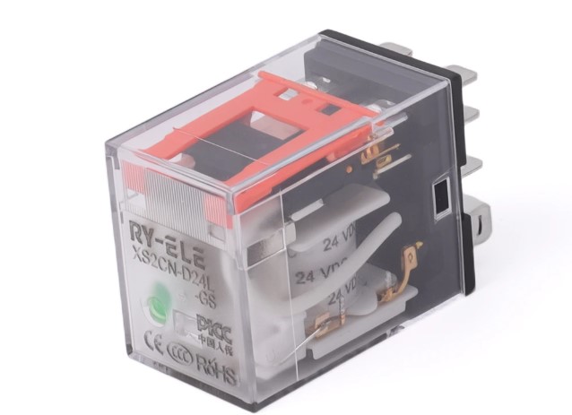
Choosing the right relay socket requires more than checking voltage and current ratings. Pin count also plays an important role because it determines how the relay connects to the circuit and whether the socket matches the relay’s terminal arrangement. A mismatch can create installation problems, wiring errors, and unnecessary redesign work.
For engineers and control-system designers, a PCB mount relay socket should match the relay’s pin configuration, electrical requirements, and PCB layout. Understanding pin count before selecting a socket helps ensure proper connections and supports reliable operation in automation and industrial equipment.
What Does Relay Pin Count Mean?
Pin count refers to the number of electrical terminals available on a relay. These terminals connect functions such as the relay coil and switching contacts to the surrounding circuit.
Different relay designs use different numbers of pins. The required count depends on the relay’s internal contact arrangement, coil configuration, and switching functions.
For example, a simple relay may use fewer terminals, while a relay with multiple contact sets may require additional pins. The socket must accommodate the same terminal pattern so the relay can seat correctly.
Why Pin Count Matters for PCB Installation
PCB-mounted components need precise positioning. A relay socket with the wrong number or arrangement of pins may not align with the holes or pads on the circuit board.
Pin configuration also affects how the socket connects to traces and other components. Even when a relay appears physically similar to another model, its terminal arrangement may differ.
Before ordering a socket, engineers should compare the relay datasheet with the socket specifications. This simple step can prevent compatibility problems during assembly.
How Pin Count Affects Relay Function
The number of pins often reflects the number of electrical functions a relay supports. Coil terminals provide the connection needed to energize the relay, while contact terminals handle the switching circuit.
A relay with more switching contacts generally needs more connection points. Selecting a socket based only on physical size can therefore lead to an incorrect match.
Engineers should identify the relay’s contact type and terminal layout first. This approach makes it easier to select a socket that supports the intended switching configuration.
Common Pin Count Considerations
Pin count varies across relay families and applications. When evaluating a socket, consider these factors:
- Coil terminals: Confirm that the socket provides the correct connections for the relay coil.
- Contact terminals: Check that the socket supports the relay’s required switching contacts.
- Pin arrangement: Compare terminal positions with the PCB footprint.
- Relay compatibility: Make sure the socket matches the specific relay series or model.
- Circuit requirements: Verify that the terminals support the required electrical load.
These checks help prevent installation issues and improve consistency during PCB assembly.
Pin Count and PCB Layout Compatibility
PCB design requires accurate component footprints. A socket with an incompatible pin layout may require changes to the board design, which can increase development time and manufacturing costs.
Engineers should verify pin spacing, terminal positions, and mounting dimensions before finalizing the PCB layout. The socket footprint should correspond closely with the manufacturer’s technical documentation.
This consideration becomes especially important in compact control panels and automated machinery where PCB space remains limited.
What Happens When the Pin Count Does Not Match?
Using a socket with an incompatible pin count can cause several practical problems. The relay may not fit into the socket, or some terminals may fail to connect to the intended PCB traces.
An incorrect configuration can also create wiring mistakes during assembly or maintenance. In some cases, engineers may need to replace the socket or modify the PCB before the system can operate correctly.
Avoiding these problems starts with checking the relay and socket specifications before purchasing components.
How Engineers Can Verify the Correct Socket
A reliable selection process should begin with the relay datasheet. Look for the terminal diagram, number of pins, contact arrangement, coil specifications, and recommended socket information.
Next, compare those details with the socket manufacturer’s documentation. Pay particular attention to the physical pin arrangement rather than relying on pin count alone.
RY-ELE provides relay and socket solutions for different control and automation applications. Engineers can use manufacturer specifications to confirm compatibility and simplify component selection.
Other Specifications to Check Alongside Pin Count
Pin count represents only one part of relay socket selection. A suitable socket should also meet the application’s electrical and mechanical requirements.
Check the following specifications before making a final decision:
- Rated voltage and current: Confirm that the socket supports the intended electrical conditions.
- Coil requirements: Match the relay’s coil configuration and operating voltage.
- Contact arrangement: Ensure compatibility with the relay’s switching function.
- Mounting method: Confirm that the socket suits the intended PCB installation.
- Material and construction: Review insulation and terminal materials for the operating environment.
- Temperature range: Check whether the socket can handle the expected working temperature.
Considering these specifications together provides a more reliable basis for component selection.
Why Pin Count Matters in Automated Machinery
Automated machinery often contains numerous relays and control circuits. A properly matched socket simplifies assembly, wiring, troubleshooting, and future replacement.
Correct pin compatibility also helps maintain consistent PCB layouts across equipment models. This can support easier production and maintenance when manufacturers use the same relay families across multiple systems.
For automation applications, careful socket selection contributes to dependable electrical connections and efficient system maintenance.
Final Thoughts
Pin count matters because it directly relates to relay compatibility, terminal functions, and PCB layout requirements. Engineers should never select a relay socket based on physical appearance alone.
Checking the pin count alongside terminal arrangement, contact configuration, electrical ratings, and mounting dimensions helps reduce installation problems. RY-ELE offers relay socket options designed for control and automation applications, giving engineers another option when evaluating compatible relay components.